|
Our "Pi_Scratch"
for scratch V1.4 driver is still
on update for new functions
& testing , it's open for free download
now, Please give us some feedback.
The main goal for this software is
towards helping children / beginner programmers /
hardware enthusiasts build up their skills by doing
simple tasks with even easier
commands / controls.
Our Program need you active your scratch
Mesh function. You can learn how to
active Mesh function
first in our link.
How to Active Mesh
Pi_Scratch_v191 --
V1.91 08,Nov 2013
Pi_Scratch_v196 --
V1.96 15,Nov 2013
Pi_Scratch_v201 -- V2.01
19,Nov 2013 Pi_Scratch_v205 --
v2.05 22,Nov 2013
Pi_Scratch_v213 -- V2.13 28,Nov 2013 Pi_Scratch_v218 -- V2.18 03,Dec 2013
Pi_Scratch_v231 -- v2.31 18,Dec 2013
Pi_Scratch_v233 -- v2.33 30,Dec 2013
Pi_Scratch_v242 -- v2.42 08,Jan 2014
Pi_Scratch_v245 -- v2.45 14,Jan 2014
Pi_Scratch_v247 -- v2.47 17,Jan 2014
Pi_Scratch_v249 -- v2.49 21,Jan 2014
Pi_Scratch_v253 -- v2.53 27,Jan 2014
Pi_Scratch_v257 -- v2.57 26,Feb 2014
Pi_Scratch_v258 -- v2.58 05,Mar 2014
Pi_Scratch_v263 --
v2.63 17,Mar 2014
Pi_Scratch_v266 -- v2.66 29,Apr 2014
-- bugs fix, function improved
Pi_Scratch_v268 -- v2.68 30,May 2014 -- bugs fix,
new function added
Pi_Scratch_v271 -- v2.71 23,Jul 2014 -- new
function added
Pi_Scratch_v272 -- v2.72 04,Aug 2014 -- bugs
fix, function improved
Pi_Scratch_v272 -- v2.72B 14,Aug
2014 -- include Model B+ support
Pi_Scratch_v273 -- v2.73 26,Sep 2014 new
function for B+ & new update for A,B & B+
Pi_Scratch_v276 -- v2.76 13,Apr 2015 new
function for B-2/A+/B+ , new update & bugs fix
Download
Pi_Scratch Software
rar
tar
format
v2.76
rar 2.4 MB tar 6.25 MB
Pi_Scratch User Manual
v2.73B PDF format
36.37MB
 User Manual v2.73B 29/09/2014 update
- Model B+ support
User Manual v2.73B 29/09/2014 update
- Model B+ support
hardware & software support detail in user manual
* Raspberry Pi
image with Pi_Scratch_v301 ready
for Raspberry Pi B2/A+/B+/3B
Download IMG Pi_Scratch_301-Pi-3.img - Raspbian
Jassie
2017-01-11
7.81GB
Pi_Scratch_301-Pi-3.img
01
02
03
04 - img to
4 zip use 7-zip
software 1.34GB
ready to use Pi_Scratch_v276B with Auto
Login & Auto Load Pi_Scratch & SSH enable --
SSH enable -- user - root password :
pi for 4GB SD card use
Win32DiskImager
1) Raspberry Pi
image with Pi_Scratch_v276 ready
for Raspberry Pi B2/A+/B+
Download IMG Pi_Scratch_276-Pi-2.img - Raspbian Wheezy
2015-02-16
3.81GB
Pi_Scratch_276-Pi-2.img
01
02
03
04 - img to
4 zip use 7-zip
software 1.34GB
ready to use Pi_Scratch_v276B with Auto
Login & Auto Load Pi_Scratch & SSH enable --
SSH enable -- user - root password :
pi for 4GB SD card use
Win32DiskImager
2) Raspberry Pi
image with Pi_Scratch_v273 ready
for Raspberry Pi B+ (B Plus)
Download IMG Pi_Scratch_v273-B.img
- Raspbian Wheezy
2014-09-09
3.81GB
Pi_Scratch_v273-B.zip
01
02
03 -
img to 3 zip use 7-zip
software 1.108GB
ready to use Pi_Scratch_v273 with Auto
Login & Auto Load Pi_Scratch & SSH enable --
SSH enable -- user - root password :
pi for 4GB SD card use
Win32DiskImager
3) Raspberry Pi
image with Pi_Scratch_v273 ready
Raspberry Pi Model A/B
Download IMG Pi_Scratch_v273.img
- Raspbian Wheezy
2014-09-09
3.81GB
Pi_Scratch_v273.zip
01
02
03 -
img to 3 zip use 7-zip
software 1.108GB
ready to use Pi_Scratch_v273 with Auto
Login & Auto Load Pi_Scratch & SSH enable --
SSH enable -- user - root password :
pi for 4GB SD card use
Win32DiskImager
4) Raspberry Pi
image with Pi_Scratch_v272 ready
Raspberry Pi Model A/B
Download IMG Pi_Scratch_v272.img
- Raspbian Wheezy
2014-01-07
3.81GB
Pi_Scratch_v272.zip
01
02
03 -
img to 3 zip use 7-zip
software 1.108GB
ready to use Pi_Scratch_v272 with Auto
Login & Auto Load Pi_Scratch --
user - root password :
pi for 4GB SD card
5)
or use the following command from your Raspberry Pi
sudo wget http://pridopia.co.uk/pi-pgm/Pi_Scratch_v276.tar
tar xf
Pi_Scratch_v276.tar
cd Pi_Scratch_v276
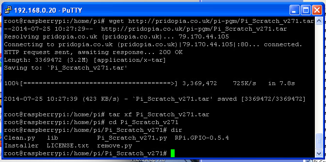
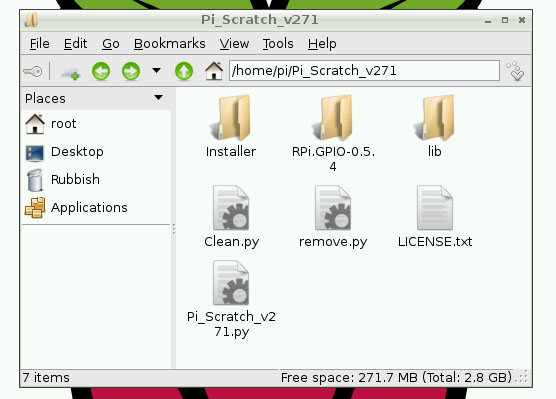
You will find folder
Pi_Scratch_v276
have 1 library folder
all library file
one License document
LICENSE.txt
One Installer folder
include three python tools
Install-With-Scratch.py & Install-Without-Scratch.py for setting
Auto Login & Auto Load Pi_Scratch ,
Install-autorun-Scratch.py
for auto load scratch example with press any key
&
one Tools install
program install.py
one main program
Pi_Scratch_v276.py
Minimum Requirements – a Raspberry Pi
with Raspbian (wheezy) installed ,
i2c function for Raspberry Pi V2.
Support 4hub/7hub i2c RTC & Temperature
sensor, AD/DA, EEPROM
i2c
8,16,32,64,128 GPIO board
spi 16,32,64,128 GPIO board
GPIO relay, DC Motor, stepper Motor ,
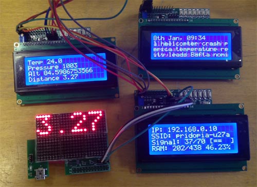
GPIO 16x2 LCD ,20x4 LCD , 84x48 LCD
i2c 16x2 LCD, i2c 20x4 LCD
i2c PWM/servo board, 16x16 ,24x16 LED matrix
1-Wire DS18B20
Temperature Sensor
i2c BMP085 Barometric
Pressure/Temperature/Altitude Sensor
Ultrasonic Distance Sensor
spi mcp3002/mcp4802 AD/DA
** New function
Maplin
USB
Robot ARM control
** New function
New i2c & GPIO LCD command ** 8,Jan 2014
DHT22
Digital
Temperature & Humidity Sensor
**
14,Jan 2014
IR-
Line Hunting sensor, IR -Flame sensor
**
14,Jan 2014
6 DOF (Degrees
of Freedom)
Servo Robot Arm
** 17,Jan 2014
IR-
PIR Motion sensor
**
20,Jan 2014
i2c PWM
LED & GPIO LED control
**
24,Jan 2014
IR remote control set
**
26,Feb 2014
Motor Wheel Encoder (Pi
GPIO) **
05,Mar 2014
i2c 23017 GPIO Motor Wheel Encoder (i2c
GPIO)
**
14,Mar 2014
24x16 & 16x16 LED Matrix new command
** 14,Mar 2014
RFID
Reader & Relay Step Motor control
**
30,May 2014
MPU6050 sensor
3 Axis Gyroscope
**
23,Jul 2014
8 DC Motor PWM control & RFID reader new update
**
26,Sep 2014
If you have any
suggestions or requirement please send an email to

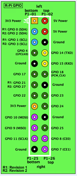
1.The pridopia Pi_Scratch use GPIO number (BCM)
not raspberry pi pin number
. so can support V2 P5 (GPIO
28,29,30,31) four extra GPIO pins.
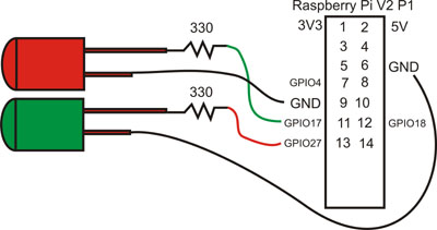
2. example 1)define GPIO
as input or output
g17out
---> GPIO17 output ( P1 pin 11)
g17in --> GPIO17 input
2) set GPIO
g17on --> GPIO17 on(High)
g17off ---> GPIO17 off(Low)
Example Program GPIO17 & GPIO27 output
---> g17-g27demo.sb /
g17-g27demo.py
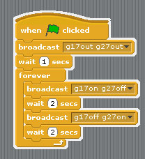
To test out control from Scratch, click on File then
Open and then click on the
Computer -> home-> pi->Pi_Scratch_Vxxx
folder and select
g17-g27demo and
click on OK. Once the
project opens, shift click "Share " choose "Host
Mesh"
or just click on the OK to enable Remote
Sensor Connections. To run the script
just click on the
Green Flag.
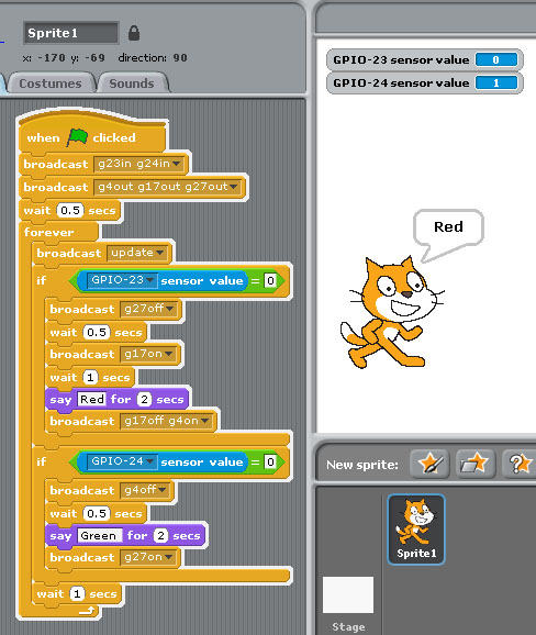
(1) GPIO input output demo
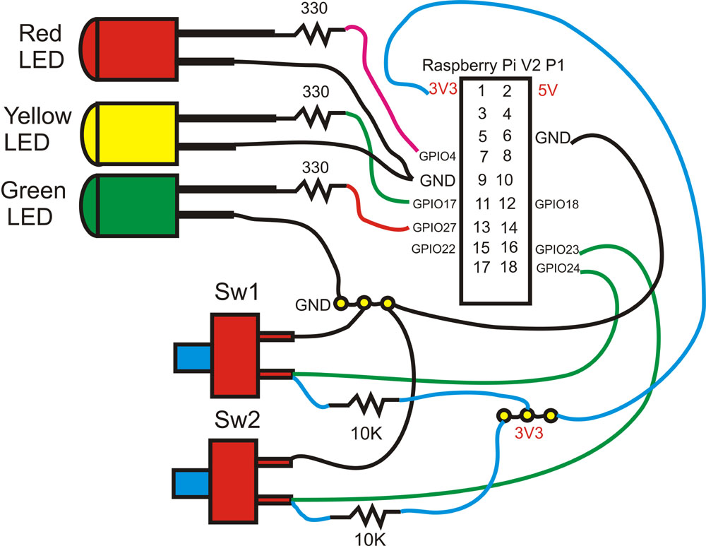
1. define GPIO 23, 24 as input
2.define GPIO 4, 17,27 as output
3. press sw2 yellow LED on 1 sec, then Red LED
"ON" The Cat say "Red"
4. press sw1 Red LED off 1 sec, then Green LED
"ON" The Cat say "Green"
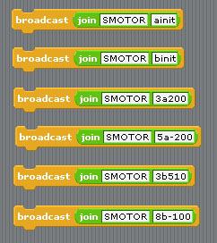
(2) GPIO Step Motor demo
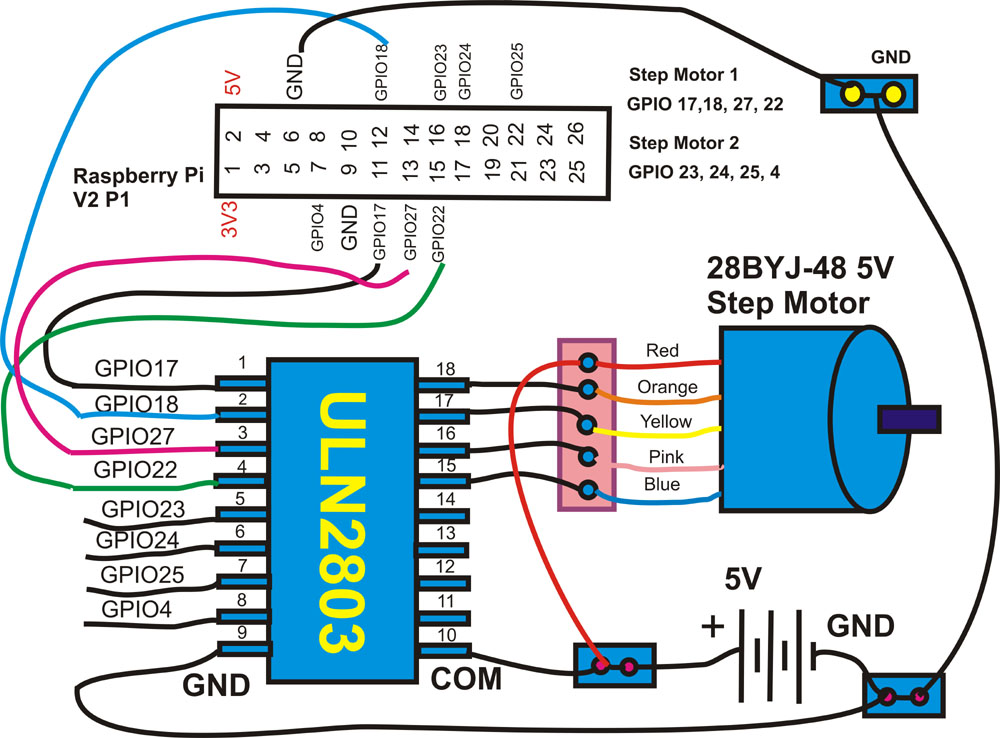
command "SMOTORainit" initial GPIO 17,18,27,22 as A Step Motor Port
command "SMOTORbinit" initial GPIO 23,24,25,7 as B Step Motor Port
command "SMOTOR" + speed (3-50) +(a or B ) + output step
100 --- clockwise 100 step , -100 --- anticlockwise 100 step
a -- GPIO 17,18,27,22 , b -- GPIO 23,24,25,4
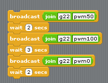
(3) GPIO DC Motor ON & Speed control demo
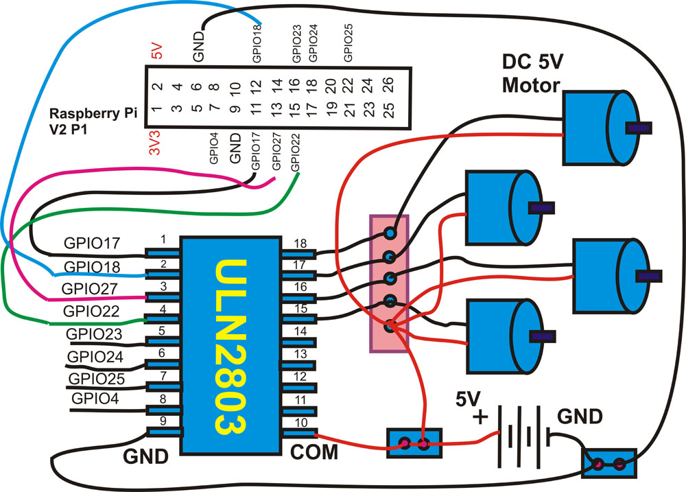
command "GPIO number"+"pwm"+"speed" speed ( 0 ~ 100)
g22pwm50 ==> GPIO 22 ON speed 50
g22pwm100 ==> GPIO 22 ON full speed 100
g22pwm0 ==> GPIO 22 ON speed 0 (STOP)
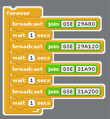
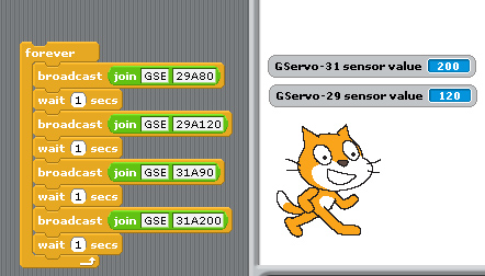
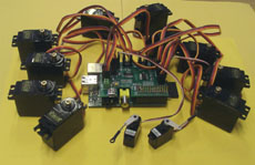
(4) GPIO DC Servo Motor control demo
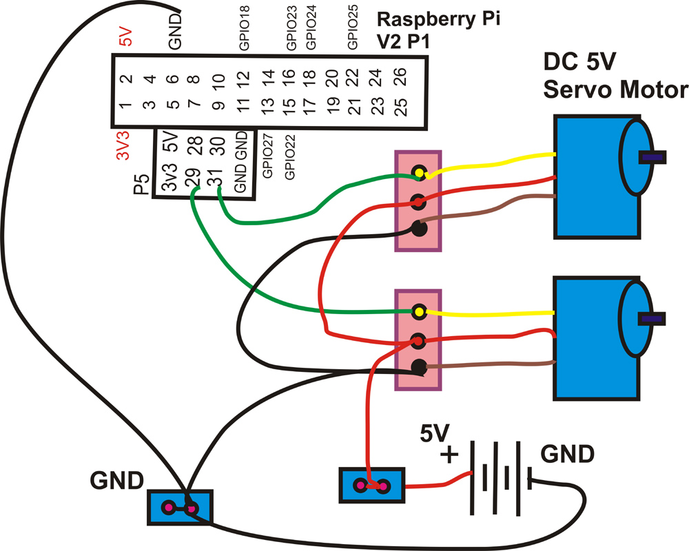
command "GSE"+"GPIO number"+"A"+"Angle" ( 55 ~ 340) GSE( GPIO Servo)
angle degree ( 55 ~ 340) depend on Servo Motor
GSE29A80 ==> GPIO 29 Servo to 80 degree
GSE29A120 ==> GPIO 29 Servo to 120 degree
GSE31A90 ==> GPIO 31 Servo to 90 degree
GSE31A200 ==> GPIO 31 Servo to 200 degree
Display the Servo Motor angle Degree Status
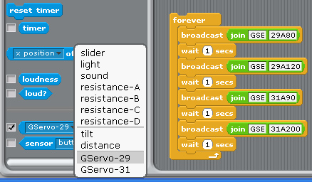
after command " GSE29A80 " ==> GPIO 29 Servo to 80 degree
command " GSE31A200 " ==> GPIO 31 Servo to 200 degree
in Sensing --> Slider , you will see the " GServo-29, & GServo-31" in the list
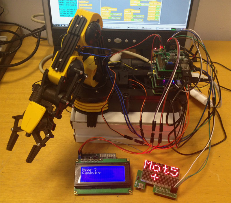
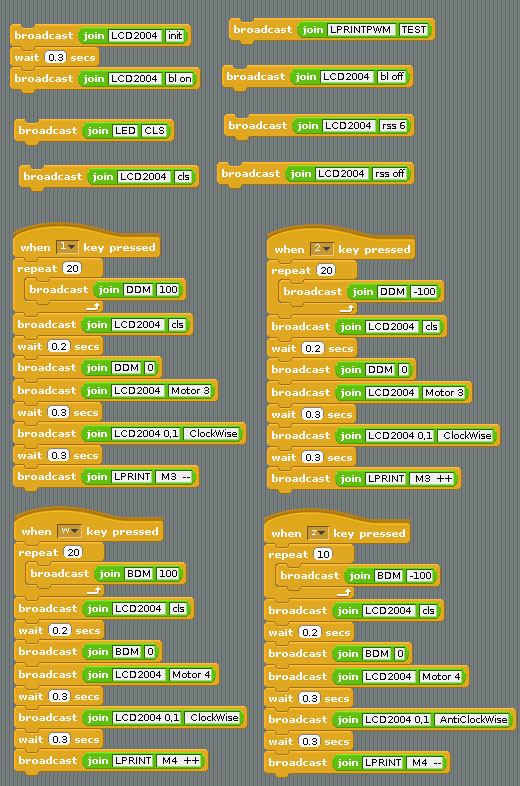
** Robot Arm control
1. Change Maplin Robot Arm from PC base,
USB port to Raspberry Pi Base,
GPIO Motor Control,
2. remove Battery use 12V DC power adapter for Raspberry Pi
and Robot Arm.
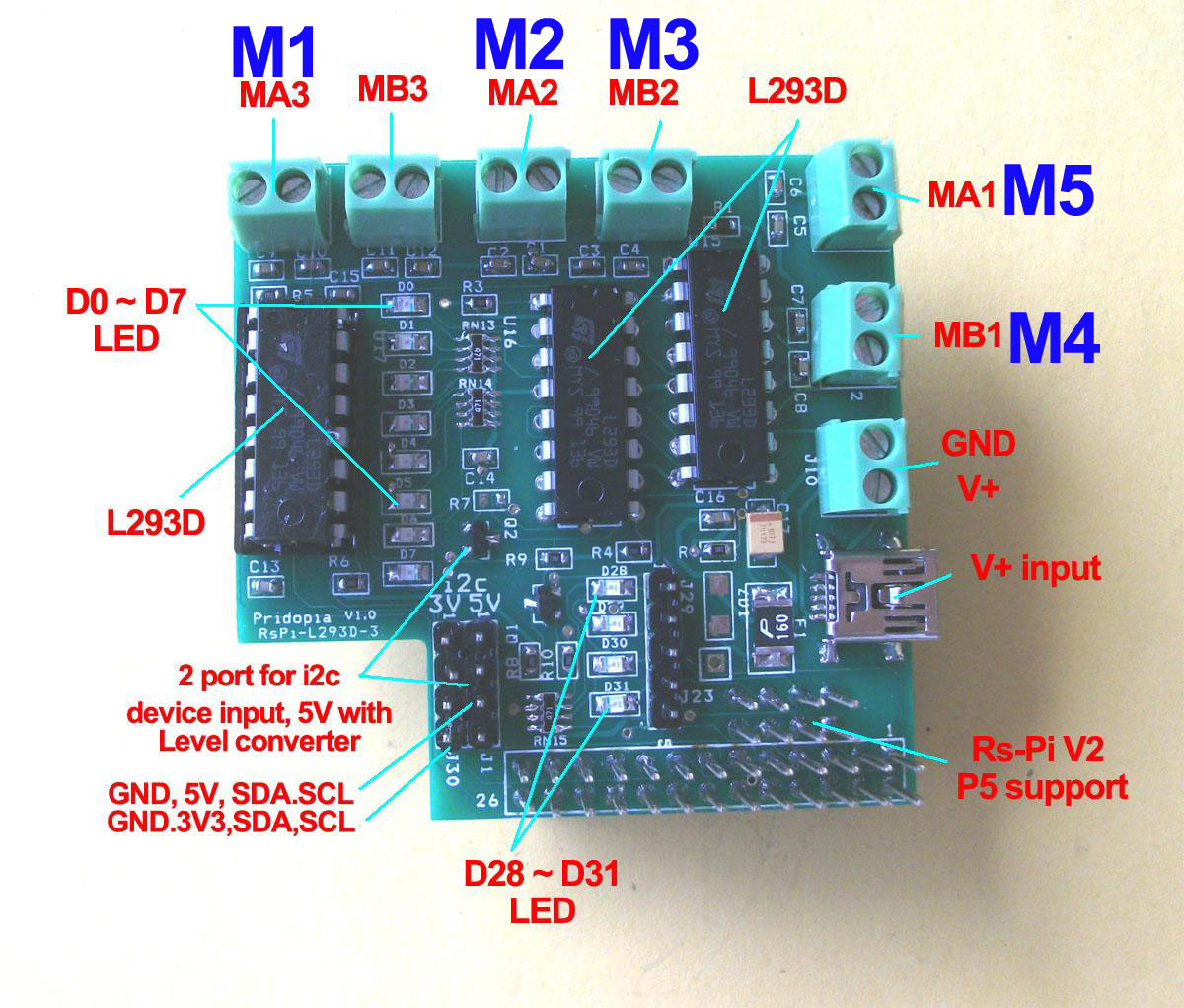
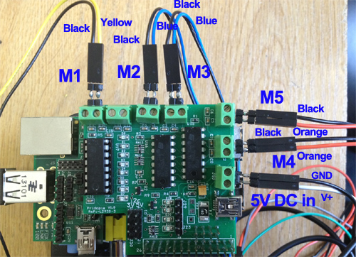
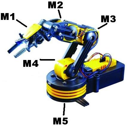
Use 1.Rs-pi–L293D-3 6 Motor Board -
Control Robot Arm 5 Motor (M1,M2,M3,M4,M5)
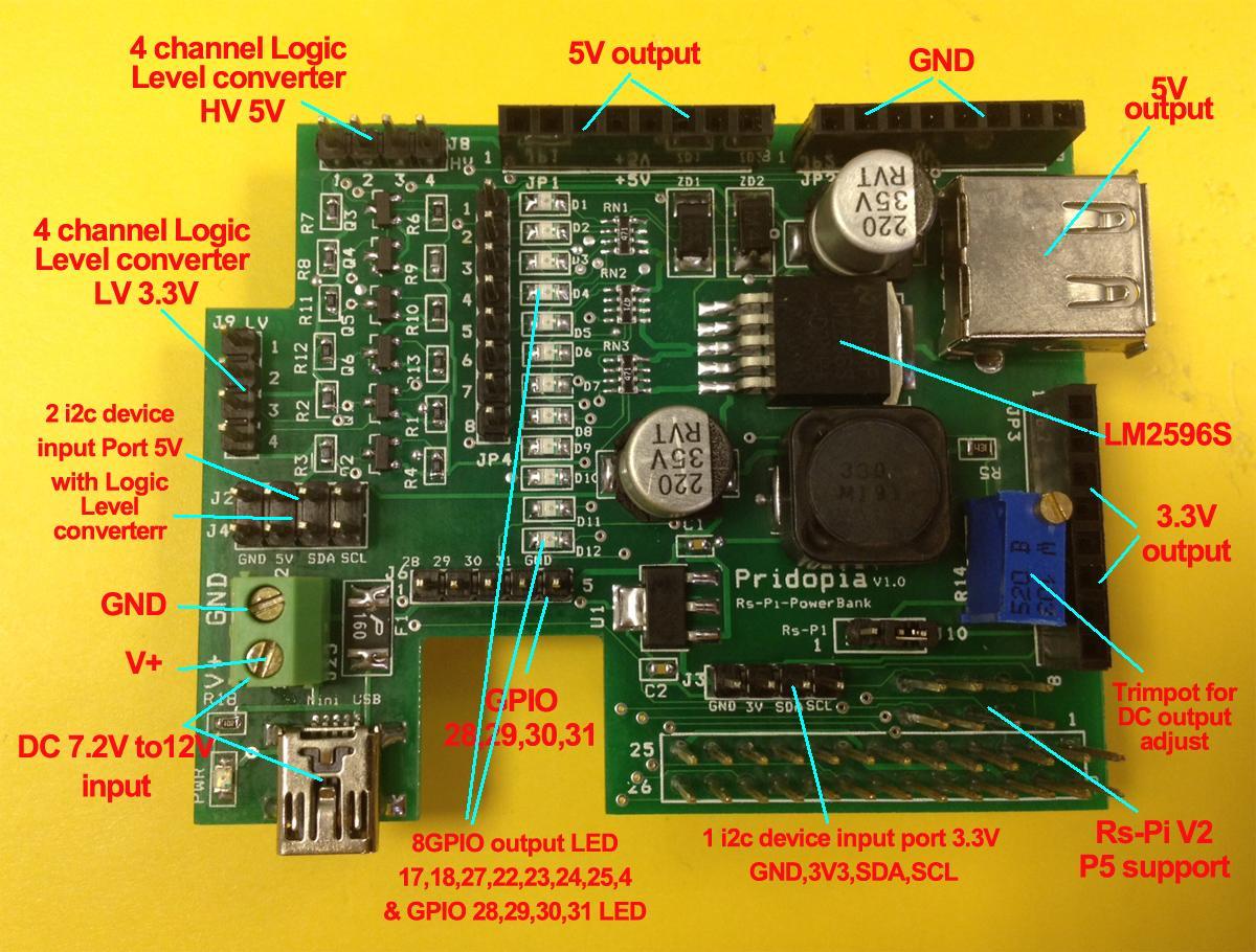
2.Rs-Pi-Power Bank Multi-function Board
Use DC12V adapter, provide Raspberry Pi 5V and
all the power for 5 DC Motor
3.Rs-Pi 4Hub i2c function Board
Provide extra USB hub & extra i2c function
(option: for Display information)
1. i2c 2004 LCD master Board
2. 24x16 LED Matrix
(1) xWindow control mode
Maplin-Arm.py use
keyboard and Mouse control
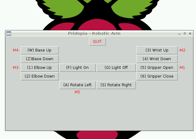
(2)Scratch GPIO control mode
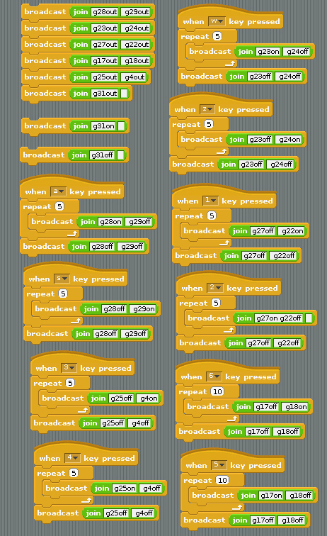
1. setting GPIO 17,18,27,22,23,24,25,4 as output
2. setting GPIO 28,29,31 as output
a KEY GPIO 28,29 M1 CLOCKWISE
s KEY GPIO 28,29 M1 ANTICLOCKWISE
w KEY GPIO 23,24 M2 CLOCKWISE
z KEY GPIO 23,24 M2 ANTICLOCKWISE
1 KEY GPIO 27,22 M4 CLOCKWISE
2 KEY GPIO 27,22 M4 ANTICLOCKWISE
3 KEY GPIO 25,4 M3 CLOCKWISE
4 KEY GPIO 25,4 M3 ANTICLOCKWISE
5 KEY GPIO 17,18 M5 CLOCKWISE
6 KEY GPIO 17,18 M5 ANTICLOCKWISE
(3)Scratch PWM command mode
A - GPIO 17,18 Motor A B - GPIO 27,22 Motor B
C - GPIO 23,24 Motor C D - GPIO 25,4 Motor D
E - GPIO 28,29 Motor E
command "Motor Name"+ "DM"+"speed"
speed (10 ~100) clockwise
speed (-10 ~ -100) anticlockwise
include information
output to display
1. i2c 20x4 LCD
display 2. i2c 24x16 LED matrix
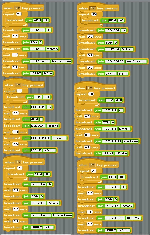
6 KEY GPIO 28,29 M1 CLOCKWISE
5 KEY GPIO 28,29 M1 ANTICLOCKWISE
3 KEY GPIO 23,24 M2 CLOCKWISE
4 KEY GPIO 23,24 M2 ANTICLOCKWISE
w KEY GPIO 27,22 M4 CLOCKWISE
z KEY GPIO 27,22 M4 ANTICLOCKWISE
2 KEY GPIO 25,4 M3 CLOCKWISE
1 KEY GPIO 25,4 M3 ANTICLOCKWISE
a KEY GPIO 17,18 M5 CLOCKWISE
s KEY GPIO 17,18 M5 ANTICLOCKWISE
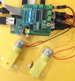
Demo1 - LED control & 2
DC Motor
control
8GPIO in P1,
4GPIO in P5 output test
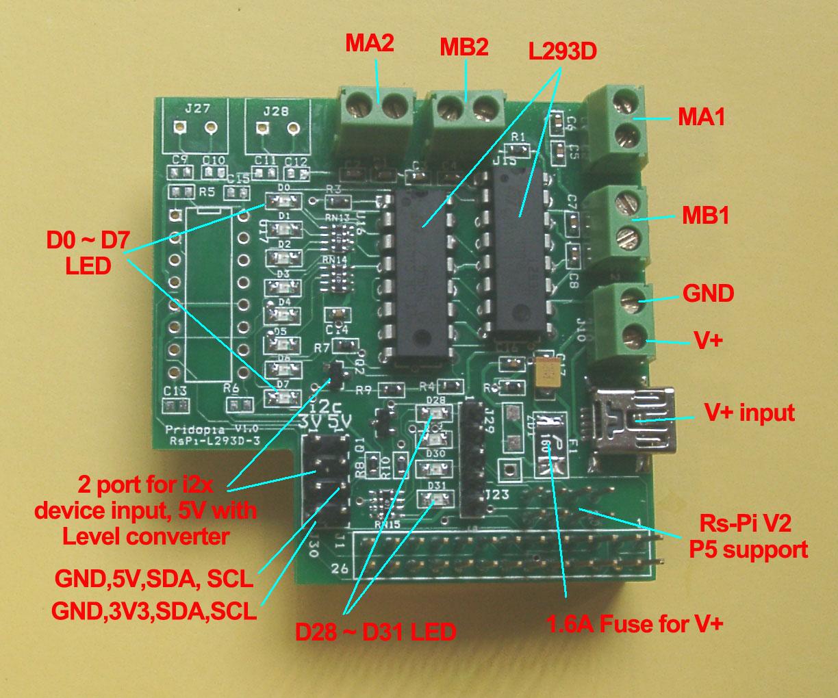
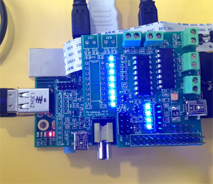
GPIO 17,18,27,22,23,24,25,4, --- p1
28,29,30,31 -- v2 p5 output demo
use our L293D-2-P5 board, with 8 LED for P1,
4 LED
for P5(28,29,30,31)
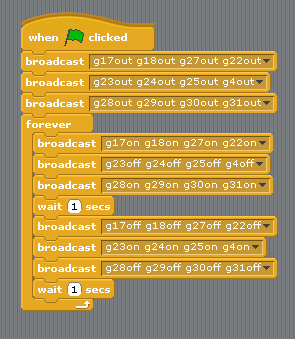
(1) LED output Test include (GPIO 28,29,30,31)
define GPIO 17,18,27,22,23,24,25,4 & 28,29,30,31 as
output
1.send GPIO 17,18,27,22 LED "ON" & 28,29,30, 31
LED "ON"
GPIO 23,24,25,4 LED "OFF"
2.send GPIO 17,18,27,22 LED "OFF" & 28,29,30, 31
LED "OFF"
gpio 23,24,25,4 LED "ON"
3. RETURN to step1
(2) 2 Motor forward, Backward, Left, Right control
& Speed test
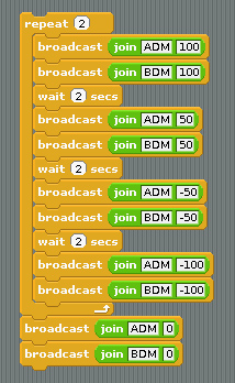
(1) Motor On Off + Speed control
A - GPIO 17,18 Motor A
B - GPIO 27,22 Motor B
C - GPIO 23,24 Motor C
D - GPIO 25,4 Motor D
command "Motor Name"+ "DM"+"speed"
"DM"( DC
Motor)
speed (10 ~100) clockwise
speed (-10 ~ -100) anticlockwise
ADM100 DC Motor A full speed 100
BDM100 DC Motor B full speed 100
ADM50 DC Motor A speed 50
BDM50 DC Motor B speed 50
ADM-100 DC Motor A anticlockwise
full speed 100
BDM-100 DC Motor B anticlockwise
full speed 100
ADM100 DC Motor A stop
BDM100 DC Motor B stop
(2) BASIC GPIO Motor on off control
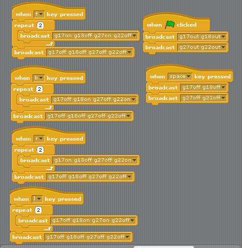
2 Motor control demo code forward, backward, turn
right, turn left. stop
define GPIO 17,18,27,22, as output
1.press keyboard " f " GPIO 17,27 LED "ON" &
18,22 LED "OFF"
car move forward
2.press keyboard " b " GPIO 18,22 LED "ON" &
17,27 LED "OFF"
car move backward
3.press keyboard " l " GPIO 18,27 LED "ON" &
17,22 LED "OFF"
car turn right
4.press keyboard " r " GPIO 17,22 LED "ON" &
18,27 LED "OFF"
car turn left
5.press keyboard " space " GPIO 17,27 LED "OFF" &
18,22 LED "OFF"
car STOP
2. Demo 2 5 GPIO Switch & 16 PWM &
4 Motor Board demo

(1) 5 GPIO Switch GPIO 7,8,9,10,11 demo
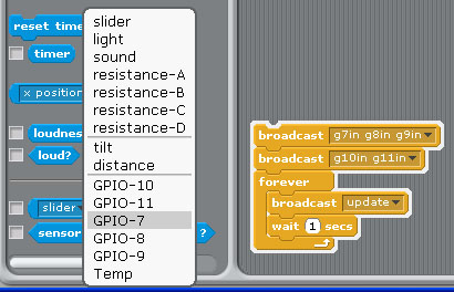
1.Setting GPIO 7,8,9,10,11 as input
2. broadcast "Update"
3. in Sensing --> Slider , you will see the GPIO-7 ,8, 9, 10,
11 in the list

(2) PWM / Servo control demo
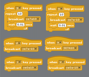
2 Servo in channel 0 & channel 7
Command "SE"+ "PWM (0-15)" + "a" +"angle" for Address 41
se7a10 --> channel 7 servo move 10 angle address 41
se7a-10 --> channel 7 servo move -10 angle address 41
se0a10 --> channel 0 servo move 10 angle address 41
se0a-10 --> channel 0 servo move -10 angle address 41
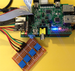
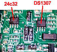
3. Demo3 detect Temperature
(i2c interface TMP102 - Temperature sensor)
i2c ds1307 RTC , i2c 23008 8
GPIO , i2c 23c32 EEPROM
i2c adc ads1015
12bit Analog-to-Digital Converter
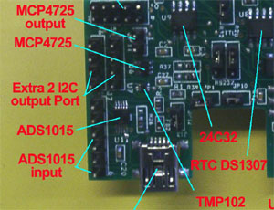
use our 4 USB Hub board with I2C RTC & TMP102 temperature
sensor
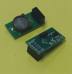
or RTC-Temp module board
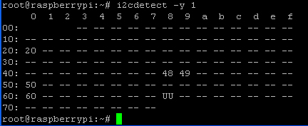
20 -> MCP23008
48 -> TMP102
68 -> RTC DS1307 50
-> 24c32
60
-> MCP4725
49-> ADS1015
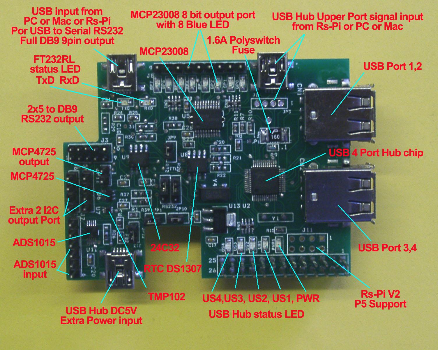
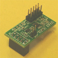
Rs-pi-4 USB Hub
AD/DA 232-R1 Rs-Pi-RTC-Temp module
(1) i2c address 48 TMP102 temperature sensor test


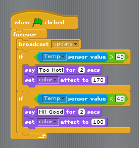
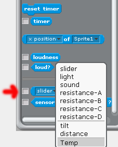
after broadcast "Update" in Sensing --> Slider , you will see the
Temp in the list
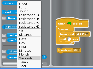
(2) i2c address 68 DS1307 RTC detect & demo
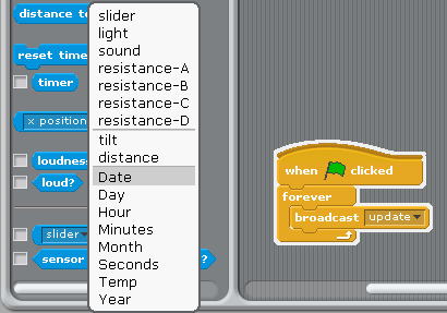
after broadcast "Update" in Sensing -->
Slider , you will see the RTC in the list
"Year, Month, Day, Date, Hour, Minutes, seconds"
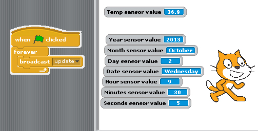
RTC information from Raspberry Pi i2c RTC
module
if you can't detect RTC function in Scratch
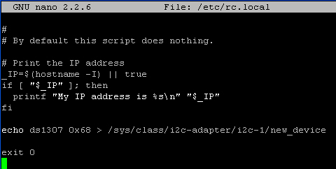
you have echo ds1307 in /etc/rc.local
in 0x68 address display "UU"
send broadcast"rtc" then
broadcast"update"
after broadcast "Update" in Sensing -->
Slider , you will see the RTC in the list
"Year, Month, Day, Date, Hour, Minutes, seconds"
(3) i2c address 20 23008 8 GPIO test
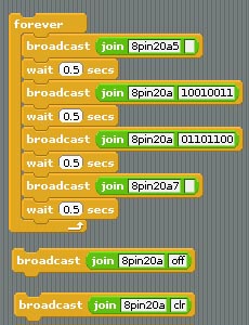
use command 8pin+"address"+a"bit (1 to 8)"
8pin+"address"+ a"10001000" --> 8bit
mode
8pin20a5 --> output
to address 20 bit 5
or use "8pin20a10010011" -->
8bit address 20 from 8 to 1 "10010011"
"8pin20aoff" or "8pin20aclr" all Port A 8bit off
(4) i2c address 49 ADC ads1015 4
channel input test
i2c adc ads1015
12bit Analog-to-Digital Converter
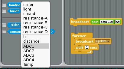
1. command
"ads1015init" initial ADS1015
2.after broadcast
"Update" in Sensing --> Slider ,
you will see the
ADC1, ADC2,ADC3, ADC4 in the list
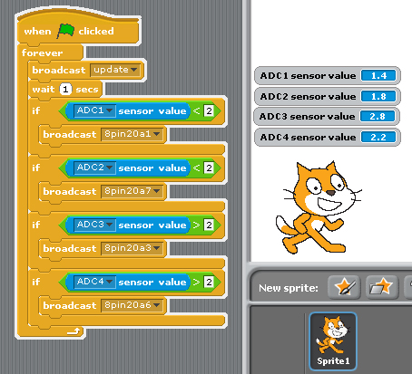
(1)adc1 input & output to 23008 8 bit GPIO bit 1
if adc1 < 2 23008 bit 1 LED "ON"
8pin20a1
(2) adc2 input & output to 23008 8 bit GPIO bit 7
if adc2 < 2 23008 bit 7 LED "ON"
8pin20a7
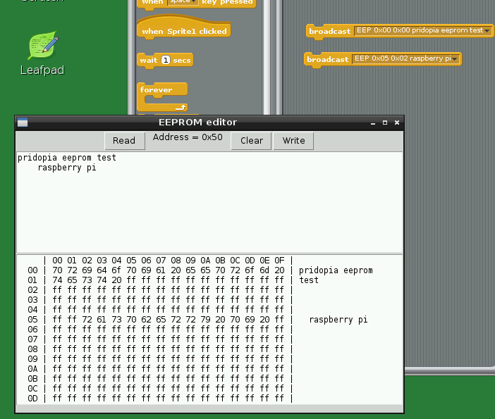
(5) EEPROM i2c address 50 24c32 read/write
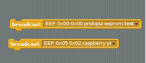
command "EEP" + start address x, start address y +
" message"
--> EEP 0x00 0x00
pridopia eeprom test
The System will open a new screen for EEPROM editor ,
need waiting about 10 seconds
(6) DAC MCP4725 12bit Digital-to-Analog Converter
JP11
(AOUT, GND) i2c address 60
demo our
4Hub/7Hub AD/DA board , AD/DA module board
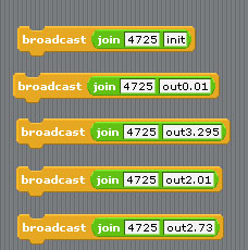
 Command "4725init" initial  DAC mcp4725
 Command "4725out" + "voltage"
voltage range "DC 0.01V to DC 3.29V"
command "4725out2.73" DC output 2.73V
4. Demo 4 1-Wire 18B20 temp Sensor
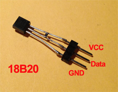
VCC to 3.3V P1 pin1, Data to P1
pin7(GPIO4) , GND to P1 pin6(GND)
Data & VCC have one 10K SMD Resister

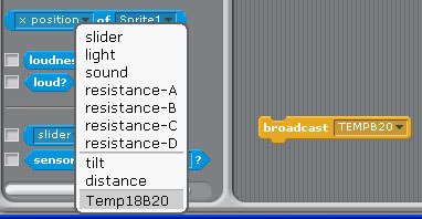
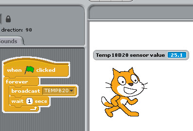
Command " TEMPB20" to active 1-wire in
pin7(GPIO4)
1.broadcast ""TEMPB20"
2. after broadcast in Sensing --> Slider ,
you will see the " Temp18B20" in the list
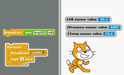
5. Demo5 i2c address 77 BMP085 sensor
BMP085 Barometric
Pressure/Temperature/Altitude Sensor
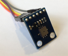

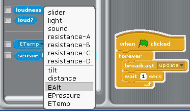
1. command "bmp085init" initial bmp085 sensor
2.
after broadcast ""Update" in Sensing --> Slider ,
you will see the " EAlt" "Epressure" "ETemp" in the list
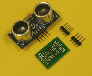
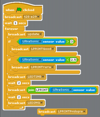
6. Demo6 Ultrasonic
distance sensor (HY-SRF05) with 2channel
Logic Level converter
Use two GPIO Trig(T) Echo(E)
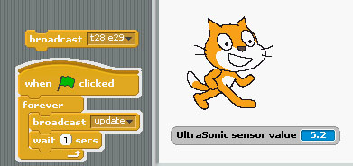
Update --> check distance and update
T28 --> Trig use
GPIO28
E29 --> Echo use GPIO29
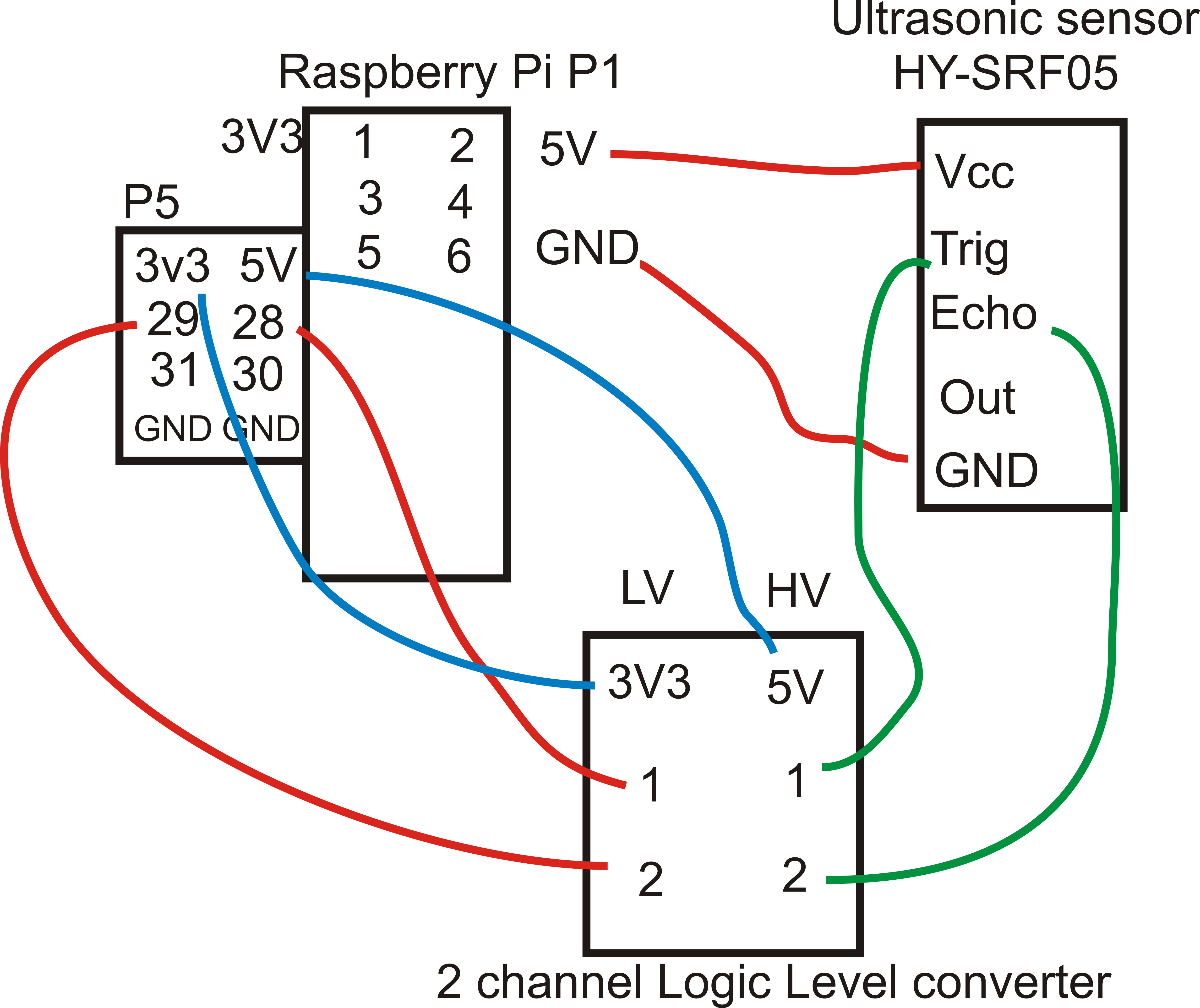
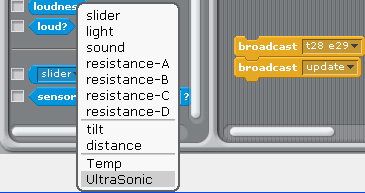
after broadcast "t28 e29 " & "Update"
T28 Trig in GPIO28 E29 Echo in GPIO29
in Sensing --> Slider , you will see the "
UltraSonic" in the list
7 Demo7 Stepper Motor and Relay control
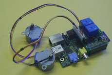
(1) command mode control step Motor
command "SMOTORainit" initial GPIO 17,18,27,22 as A Step Motor Port
command "SMOTORbinit" initial GPIO 23,24,25,7 as B Step Motor Port
command "SMOTOR" + speed (3-50) +(a or B ) + output step
100 --- clockwise 100 step , -100 --- anticlockwise 100 step
a -- GPIO 17,18,27,22 , b -- GPIO 23,24,25,4
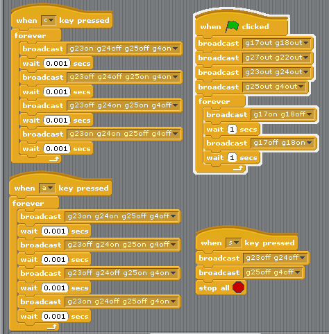
(2) GPIO pin mode control Step Motor
main program turn relay 1,on 2 off -> 1 off, 2 on
on cycle
press C Stepper Motor clockwise
press A Stepper Motor anticlockwise
Press S Stop
8. Demo8 Input & output test
1.Setting GPIO (17,18,27,22,23,24,25,4) as input
control Switch 1 to 8 ,
2. broadcast "Update"
3. in Sensing --> Slider , you will see the GPIO
17,18,27,22,23,24,25,4 in the list
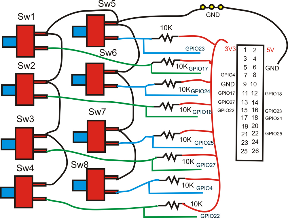
Detect GPIO (17,18,27,22,23,24,25,4) switch status
Press GPIO17 input switch output to GPIO28 LED
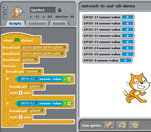
9. Demo9 Input & i2c 23017 16 GPIO & 16 LED output test
& Stepper Motor Test
1.Setting GPIO 17 as input control Switch 1
2. broadcast "Update"
3. in Sensing --> Slider , you will see the GPIO
17 in the list
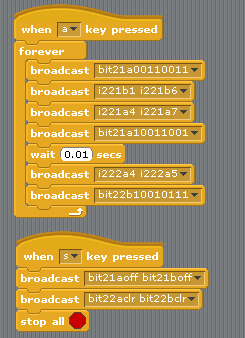
(1) switch input & i2c 16 GPIO output
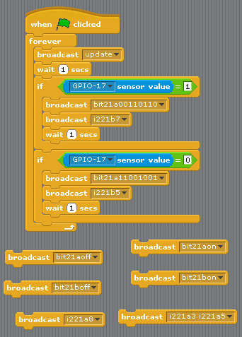
set GPIO17 as input, output to i2c Port A/B
You can use "bit21aon" or "bit21bon"
i2c 23017 address 21 PortA ,B 16LED all on
You can use "bit21aoff" or "bit21boff"
i2c 23017 address 21 Port A/B 16LED all off
or use "bit21a01100000" address 21 Port A bit 7,6 on
use "bit21a10011111" address 21 Port A bit 8,5,4,3,2,1 on
"i221a8" i2c address 21 port A bit 8 on
"i221a5" i2c address 21 port A bit 5 on
"i221b3" i2c address 21 port B bit 3 on
"i221b8" i2c address 21 port B bit 8 on
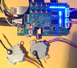
(2) Stepper Motor Test
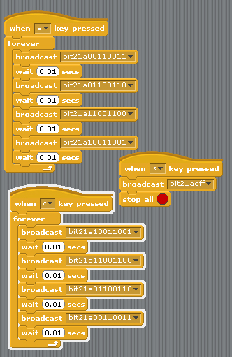
press C address 21 GPIO Stepper Motor clockwise
press A address 21
GPIO Stepper Motor anticlockwise
Press S Stop
10. Demo10 i2c 16 channel PWM & i2c 23017 16 GPIO test
(1) Servo Motor control
2 Servo in channel 0 & channel 7
Command "SE"+ "PWM (0-15)" + "a" +"angle" for Address 41
se7a10 --> channel 7 servo move 10 angle address 41
se7a-10 --> channel 7 servo move -10 angle address 41
se0a10 --> channel 0 servo move 10 angle address 41
se0a-10 --> channel 0 servo move -10 angle address 41
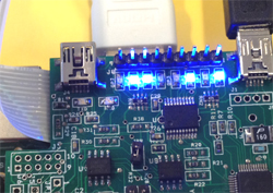
(2) PWM LED output demo
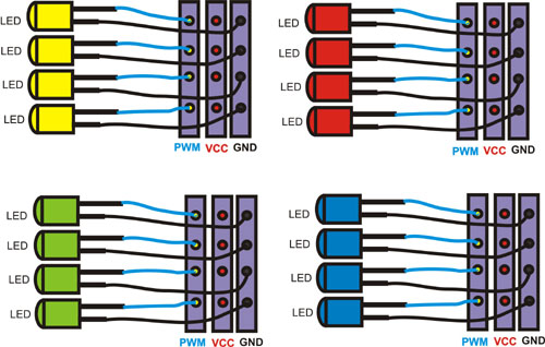
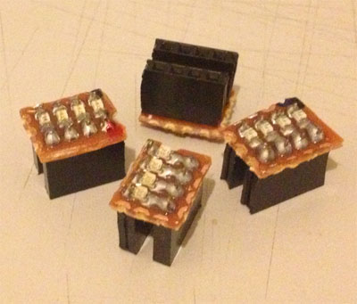
LED module (Blue, Green,Yellow,Red)
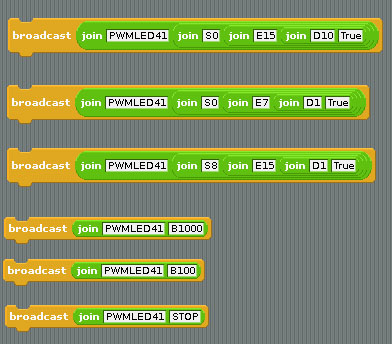
LED Scrolling Command PWMLED41S0E15D4True
PWMLED”Address” S[Start channel] E[End channel] D[Delay / Timing] [True/False]
Address 41, 42,43,44
Start channel & End channel 0 ~ 15 16 channel
D 1,2,3,4,5 (1 ~ 100) Delay Timing
LED Brightness control Command
PWMLED “Address” “B” “0 ~ 1000“
PWMLED41B1000
Stop command
PWMLED41stop
11. Demo11 i2c 32 channel PWM Test
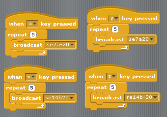
Command "SE"+ "PWM (0-15)" + "a" +"angle" for Address 41
Command "SE"+ "PWM (0-15)" + "b" +"angle" for Address 40
se7a20 --> channel 7 servo move 20 angle address 41
se7a-20 --> channel 7 servo move -20 angle address 41
se14b20 --> channel 14 servo move 20 angle address 40
se14b-20 --> channel 14 servo move -20 angle address 40
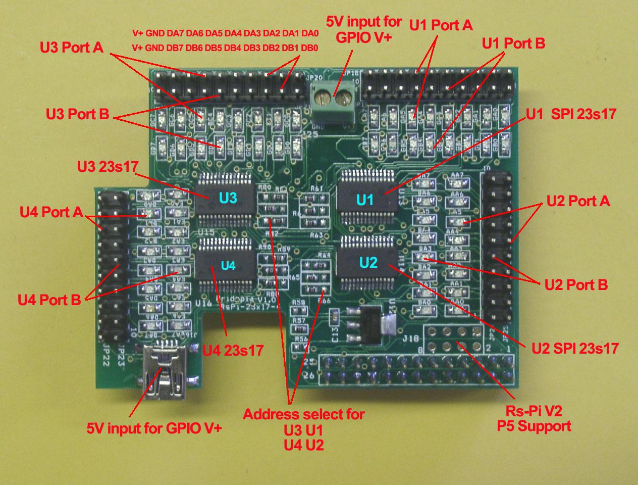
12. Demo12 i2c 23017-4 64 GPIO & 64 LED output test
 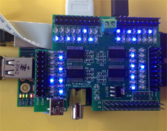
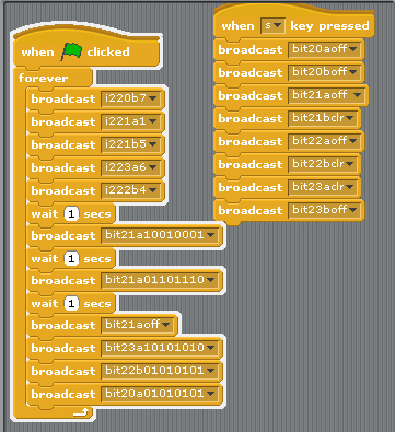
U1 to U4 i2c 23017 address 20,21,22,23
Command "i2"+ "address(20-27)" + "a" +"bit(1 to 8)" for Port A
Command "i2"+ "address(20-27)" + "b" +"bit(1 to 8)" for Port B
Command "bit"+ "address(20-27)" + "a" +"bit(8 to 1)" for Port A
Command "bit"+ "address(20-27)" + "b" +"bit(8 to 1)" for Port B
i221a1 --> i2c address 21 Port A bit 1 ON/OFF
i220b7 --> i2c address 20 Port B bit 7 ON/OFF
i222b4 --> i2c address 22 Port B bit 4 ON/OFF
bit22b01010101 --> address 22 port B from bit 8 to 1
output --> 01010101
bit20a01010101 --> address 20 port A from bit 8 to 1
output --> 01010101
bit21aoff --> address 21 Port A all OFF/clear
bit23aclr --> address 23 Port A all OFF/clear
13. Demo13 i2c 23017-2 32 GPIO & 32 LED output test
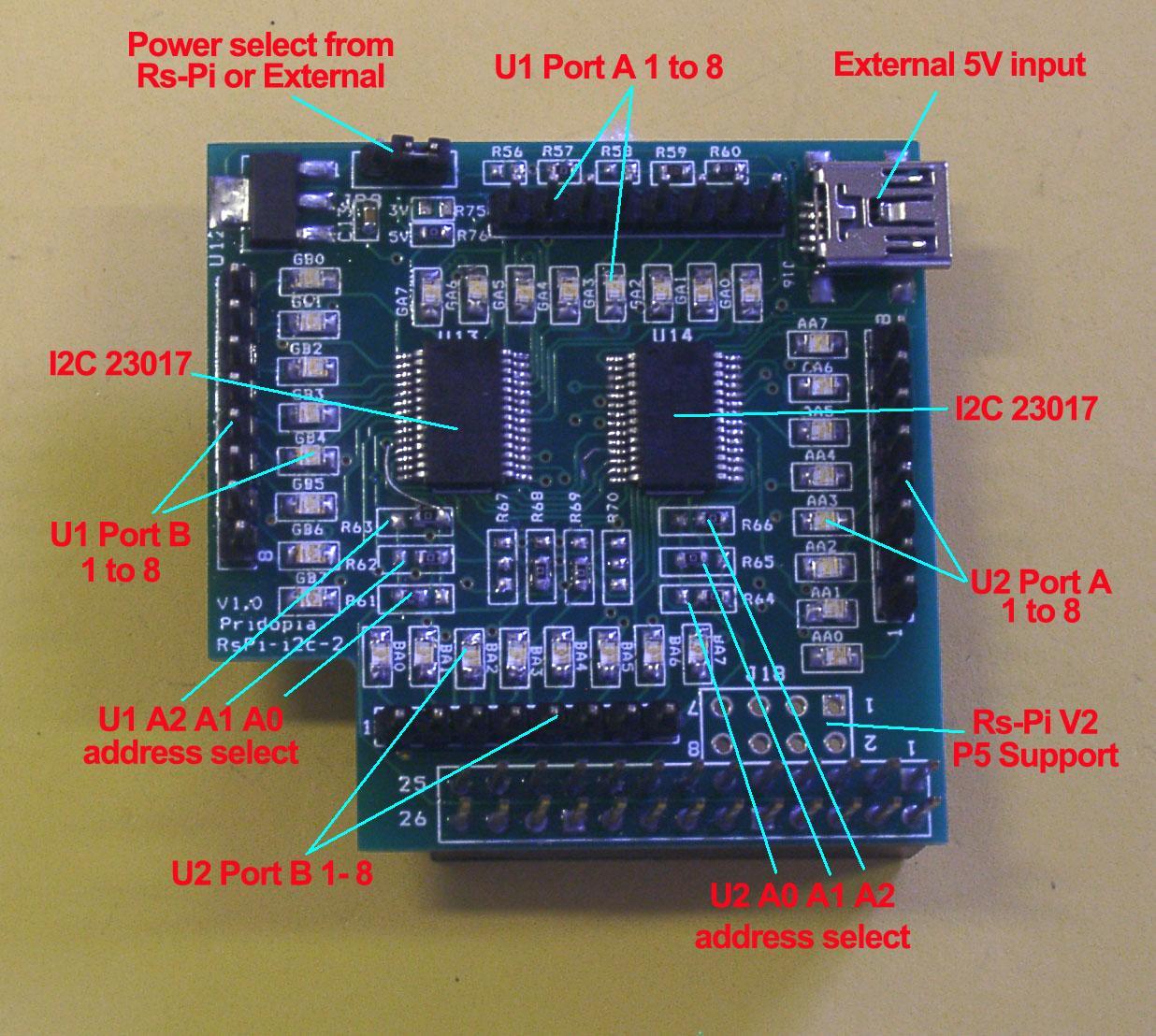
U1 to U2 i2c 23017 address 21,22
Command "i2"+ "address(20-27)" + "a" +"bit(1 to 8)" for Port A
Command "i2"+ "address(20-27)" + "b" +"bit(1 to 8)" for Port B
Command "bit"+ "address(20-27)" + "a" +"bit(8 to 1)" for Port A
Command "bit"+ "address(20-27)" + "b" +"bit(8 to 1)" for Port B
i221a1 --> i2c address 21 Port A bit 1 ON/OFF
i222b4 --> i2c address 22 Port B bit 4 ON/OFF
bit22b01010101 --> address 22 port B from bit 8 to 1
output --> 01010101
bit21a01010101 --> address 21 port A from bit 8 to 1
output --> 01010101
bit21aoff --> address 21 Port A all OFF/clear
bit21boff --> address 21 Port B all OFF/clear
bit22aoff --> address 22 Port A all OFF/clear
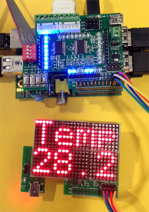
14.Demo 14 i2c 23017-2803 Switch input test
(1)
i2c 32GPIO & 8 switch input
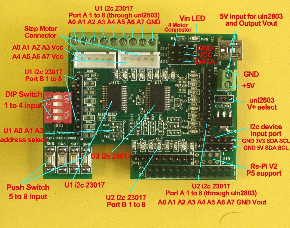
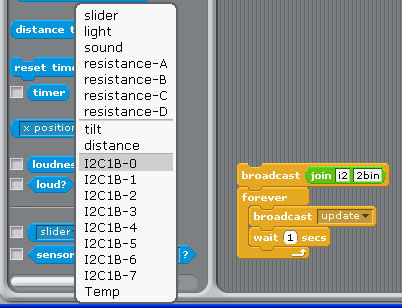
 Command "i2"+ "address(1-8)" + "a" +"in" for Port A
 Command "i2"+ "address(1-8)" + "b" +"in" for Port B
Address 20 --> 1 21 --> 2 22-->3 23 -->4
Address 24 --> 5 25 --> 6 26-->7 27 -->8
command "i22bin" initial address 21, Port B as input
(1)"i22bin" initial address 21, Port B as input
(2) broadcast "Update"
(3) in Sensing --> Slider , you will see the "
I2C1B-0 ~ I2C1B-7" in the list
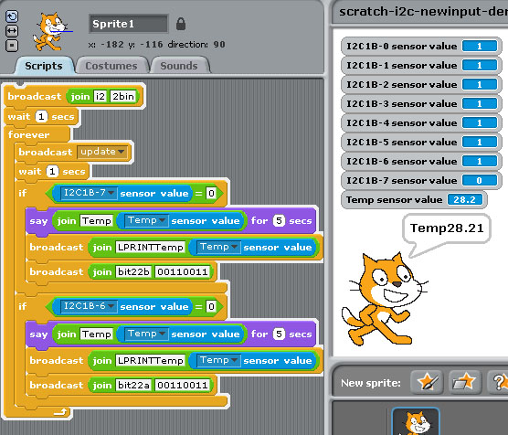
The demo use i2c 24x16 LED Matrix for output message
i2c TMP102 for temperature sensor
i2c 23017 address 21 port B for 8 switch input
i2c 23017 address 22 port A/B for output
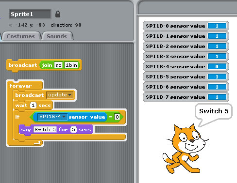
(2) spi 23s17-2 8 Switch input
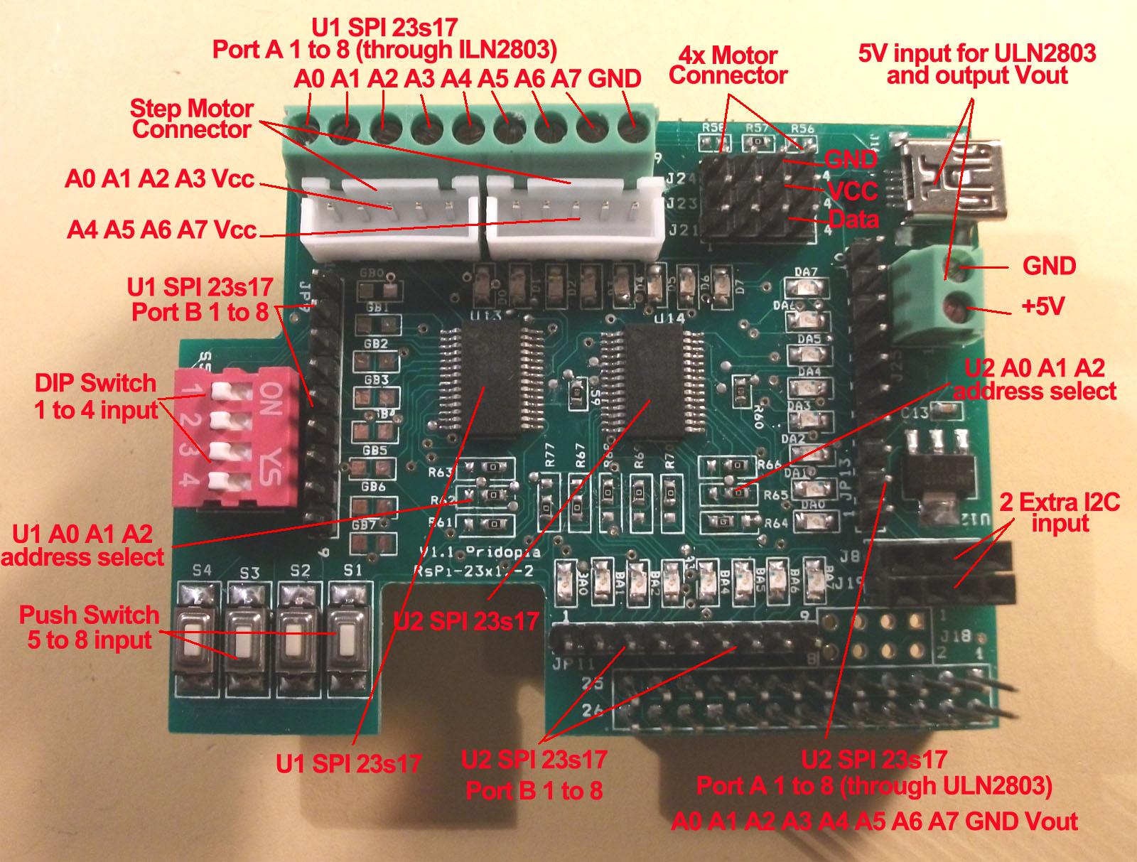
U1 to U2 spi 23s17 address 40,42,44,46
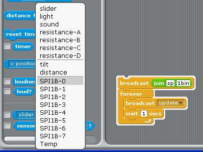
 Command "sp"+ "address(1-8)" + "a" +"in" for Port A
 Command "sp"+ "address(1-8)" + "b" +"in" for Port B
 command "sp1bin" initial address 40, Port B as input
 broadcast "Update" in Sensing ---> Slider ,
you will see "SPI1B-0 ~ SPI1B-7" in the list
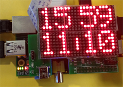
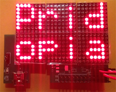
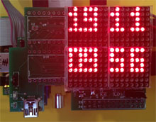
15. Demo15 24x16 & 16x16 LED matrix
(1)24x16 LED Matrix
(1)
command LED+ "TIME" display Time &
Date
(2)
command LED+ "IMG" display 24X16
image & Time/Date
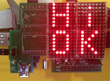
(3) command LED + "message" display message
LEDthis is led matrix demo -->
display "this is led matrix demo"
(4) command "LEDCLS" clean
24x16 screen
(4) command LPRINT + "message"
Maximum display message 5X7 8 character in 24x16 Matrix
(2) 16x16 LED Matrix
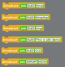
(1) command SLED+
"time" display Time & Date (3x5 font)
(2) command SLED+ "img"
display 16X16 image
(3) command SLED +
"message" display message
SLEDthis is led matrix
demo --> display "this is led matrix demo"
(4) command "SLEDCLS" clean 16x16
screen
(5) command SPRINT +
"message"
Maximum display
message 5X7 4 character in 16x16 Matrix
16. Demo16 GPIO 84x48 LCD , GPIO 16x2 LCD, GPIO 20x4
LCD
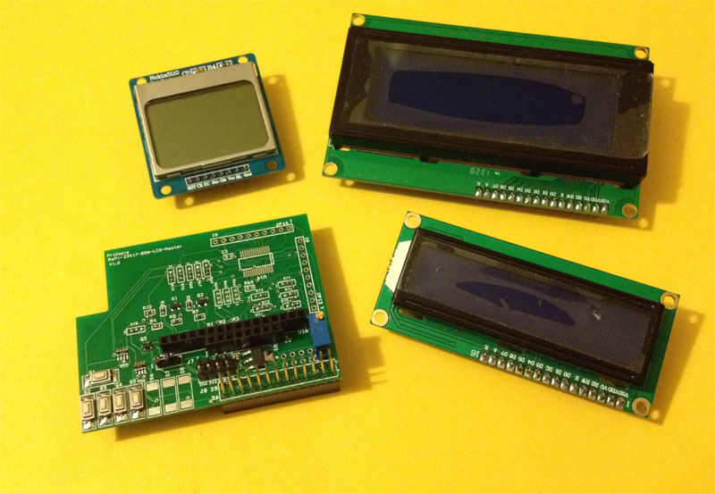
our Rs-Pi LCD Master can plug-in 84x48 LCD , 16x2 LCD,
20x4 LCD
(1) 5 GPIO Switch GPIO 7,8,9,10,11
1.Setting GPIO 7,8,9,10,11 as input
2. broadcast "Update"
3. in Sensing --> Slider , you will see the GPIO-7 ,8, 9, 10,
11 in the list
(2) 84x48 pixels LCD
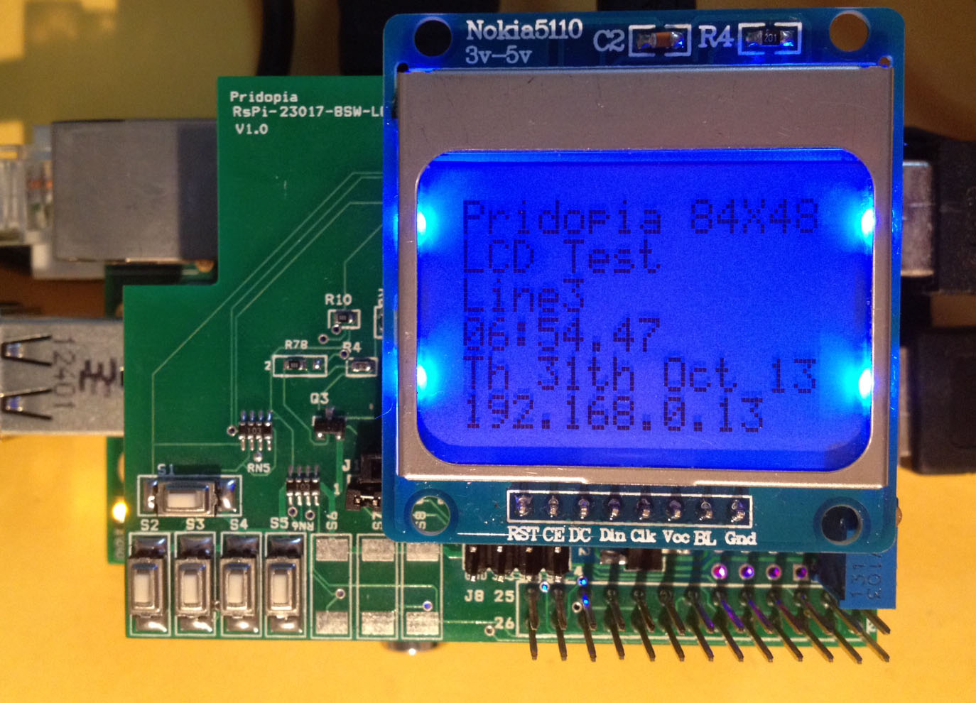
command "LCD8544 " + "init"
initial 84x48 LCD
command "LCD8544 " + "con " + " (0 -255)"
LCD contrast
command "LCD8544 " + "bl " + "on/off"
LCD back light ON / OFF
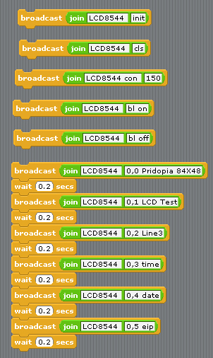
command "LCD8544 " + "cls" clean screen
command "LCD8544 " + "X , Y " + " MESSAGE"
Display message to LCD in location x,y
command "LCD8544 " + "X , Y " + "
wip"
Display WiFi IP to LCD in location x,y
command "LCD8544 " + "X , Y " + "
eip"
Display Ethernet IP to LCD in location x,y
command "LCD8544" + "X , Y " + "
time"
Display Time to LCD in location x,y
command "LCD8544 " + "X , Y " + "
date"
Display Time to LCD in location x,y
LCD 84x48 Top 5 news from BBC RSS
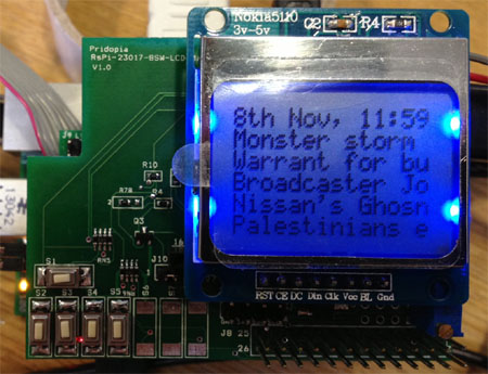
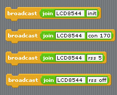
command "LCD8544 init" initial GPIO
84x48 LCD
command "LCD8544 con 170" (0 -255)"
LCD contrast
command "LCD8544 "rss"+ " speed" Active RSS function
(need have internet)
LCD8544 rss 5
speed (1 to 20 - 1 is fast , 20 is slow)
command "LCD8544 rss off" stop RSS function
(3) 20x4 Character LCD
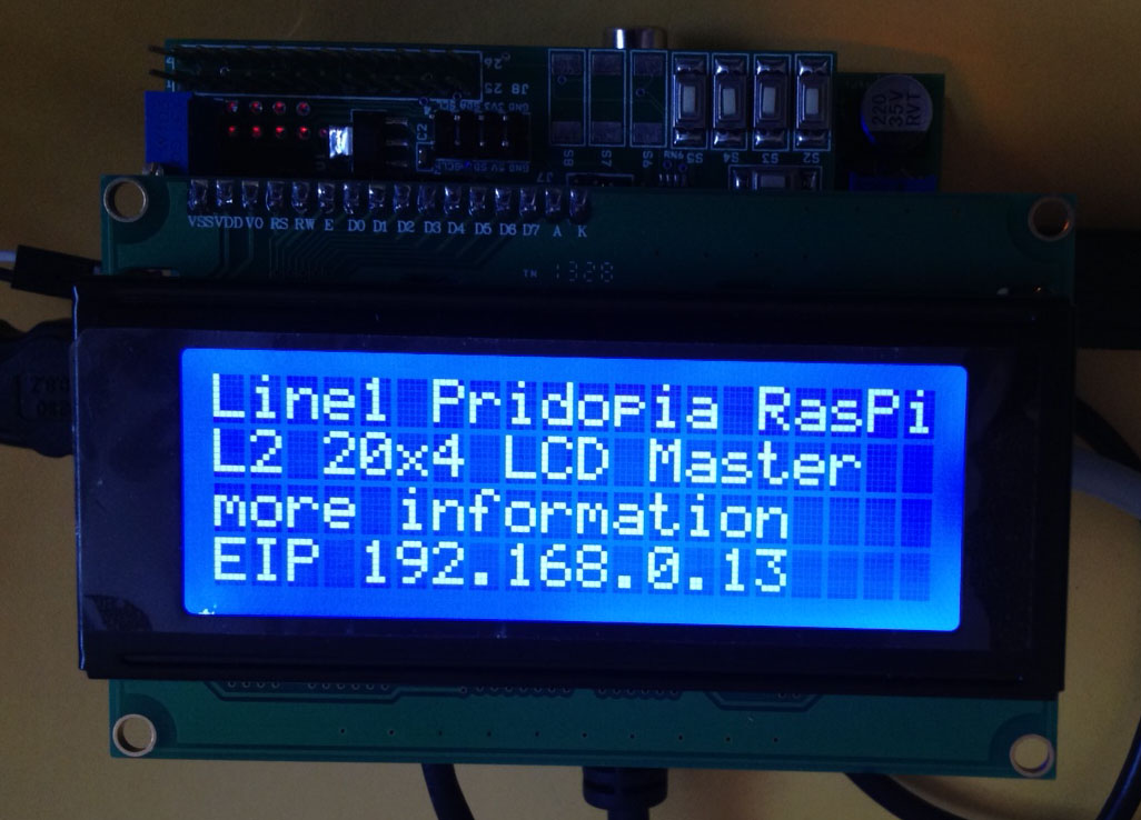
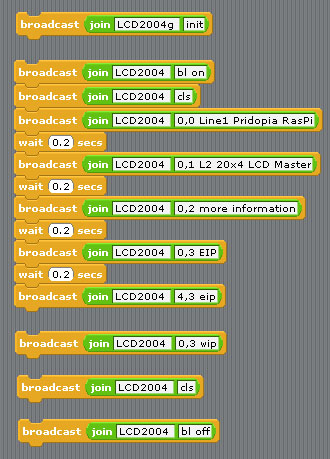
command "LCD2004g " + "init" initial
GPIO 20x4 LCD
command "LCD2004 " + "X , Y " + " MESSAGE"
Display message to LCD in location x,y
command "LCD2004 " + "cls" clean screen
command "LCD2004 " + "bl " + "on/off"
LCD back light ON / OFF
command "LCD2004 " + "X , Y " + " wip"
Display WiFi IP to LCD in location x,y
command "LCD2004 " + "X , Y " + " eip"
Display Ethernet IP to LCD in location x,y
command "LCD2004 " + "X , Y " + "
time"
Display Time to LCD in location x,y
command "LCD2004" + "X , Y " + "
date"
Display Time to LCD in location x,y
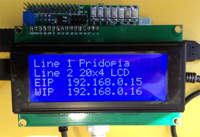
(4) 20x4 Character LCD
RSS function ( Scrolling text Display top 3 News
message)
BBC world news RSS feed
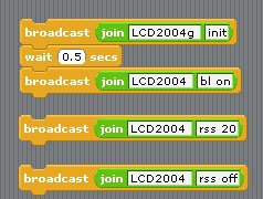
command "LCD2004g init" initial GPIO 20x4 LCD
command "LCD2004 bl on" Turn On LCD back light
command "LCD2004 "rss"+ " speed" Active RSS function
(need have internet)
LCD2004 rss 5
speed (1 to 20 - 1 is fast , 20 is slow)
command "LCD2004 rss off" stop RSS function
Date & Time in first Line, 2,3,4 line show top 3 BBC RSS
news
(5) 16x2 Character LCD
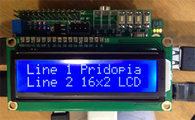
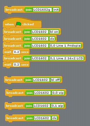
command "LCD1602g " + "init" initial
GPIO 16x2 LCD
command "LCD1602 " + "X , Y " + " MESSAGE"
Display message to LCD in location x,y
command "LCD1602 " + "cls" clean screen
command "LCD1602 " + "bl " + "on/off"
LCD back light ON / OFF
command "LCD1602 " + "X , Y " + " wip"
Display WiFi IP to LCD in location x,y
command "LCD1602 " + "X , Y " + " eip"
Display Ethernet IP to LCD in location x,y
command "LCD1602 " + "X , Y " + "
time"
Display Time to LCD in location x,y
command "LCD1602 " + "X , Y " + "
date"
Display Time to LCD in location x,y
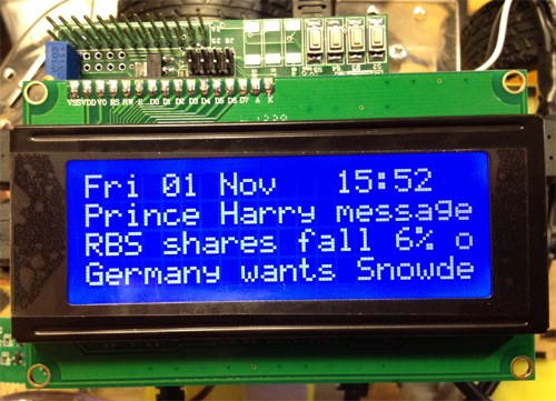
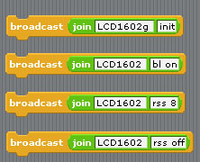
16x2 RSS function
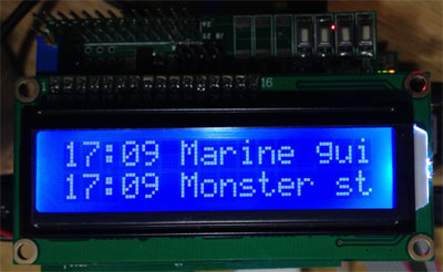
RSS function ( Scrolling text Display top 4 News
message)
message format
Line1 --> Time + message 1 + " ->-> "
+ Message 3 + Time
Line2 --> Time + message 2 + " ->-> " +
Message 4 + Time
BBC world news RSS feed
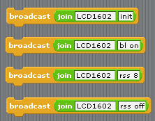
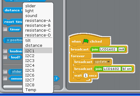
command "LCD1602g init" initial GPIO 16x2 LCD
command "LCD1602 bl on" turn on LCD back light
command "LCD1602 "rss"+ " speed" Active RSS function
(need have internet)
LCD1602 rss 8
speed (1 to 20 - 1 is fast , 20 is slow)
command "LCD1602 rss off" stop RSS function
17. Demo17 GPIO 84x48 LCD , i2c 16x2 LCD, i2c 20x4 LCD
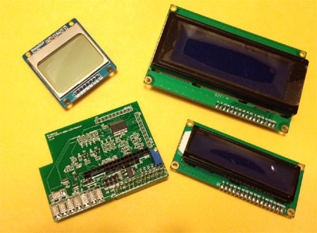
our Rs-Pi i2c LCD Master can plug-in 84x48 LCD , 16x2 LCD,
20x4 LCD
(1) i2c 20x4 character LCD
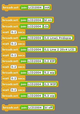
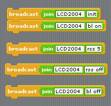
command "LCD2004 " + "init" initial
i2c 20x4 LCD
command "LCD2004 " + "X , Y " + " MESSAGE"
Display message to LCD in location x,y
command "LCD2004 " + "cls" clean screen
command "LCD2004 " + "bl " + "on/off"
LCD back light ON / OFF
command "LCD2004 " + "X , Y " + " wip"
Display WiFi IP to LCD in location x,y
command "LCD2004 " + "X , Y " + " eip"
Display Ethernet IP to LCD in location x,y
command "LCD2004 " + "X , Y " + "
time"
Display Time to LCD in location x,y
command "LCD2004" + "X , Y " + "
date"
Display Time to LCD in location x,y
(2) 20x4 RSS function
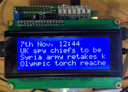
RSS function ( Scrolling text Display top 3 News
message)
BBC world news RSS feed
command "LCD2004 init" initial i2c 20x4 LCD
command "LCD2004 bl on" turn on LCD back light
command "LCD2004 "rss"+ " speed" Active RSS function
(need have internet)
LCD2004 rss 5
speed (1 to 20 - 1 is fast , 20 is slow)
command "LCD2004 rss off" stop RSS function
(3)new command - 08,Jan, 2014 update
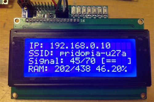
command "LCD2004 " +
"X , Y " + " ram" Display RAM usage in location x,y
command "LCD2004 " +
"X , Y " + " wifi” + “ ip” Display WiFi IP in
location x,y
command "LCD2004 " +
"X , Y " + " wifi"+" ssid" Display WiFi SSID in location x,y
command "LCD2004 " +
"X , Y " + " wifi"+ " gsig" Display wifi signal with bar chart
in location x,y
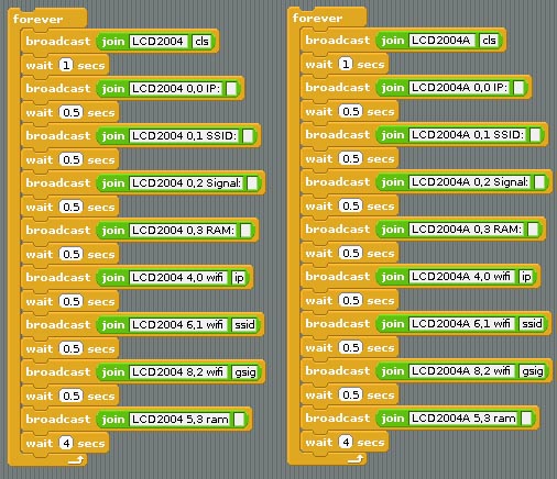
also work with i2c LCD module ”LCD2004A” ,”LCD2004B”,
”LCD2004C” ,”LCD2004D”
(4) Multi i2c 20x4 LCD module
A = ADDRESS 24, B =
ADDRESS 25, C = ADDRESS 26, D = ADDRESS 27
command "LCD2004 " +
"init" initial i2c 20x4 LCD address 21
command "LCD2004A " +
"init" initial i2c 20x4 LCD address 24
command "LCD2004B " +
"init" initial i2c 20x4 LCD address 25
command "LCD2004C " +
"init" initial i2c 20x4 LCD address 26
command "LCD2004D " +
"init" initial i2c 20x4 LCD address 27
command "LCD2004"
“Address” + "X , Y " + " MESSAGE" Display message in
location x,y
command "LCD2004" +
”address” +" cls" clean screen
command "LCD2004"
+”address” + "bl " + "on/off" LCD back light ON / OFF
command "LCD2004" +
”address” +"X , Y " + " wip" Display WiFi IP to LCD
in location x,y
command "LCD2004"
+”address” + "X , Y " + " eip" Display Ethernet IP to
LCD in location x,y
command "LCD2004"
+”address” + "X , Y " + " time" Display Time to LCD in
location x,y
command "LCD2004" +
”address” +"X , Y " + " date" Display Time to LCD in
location x,y
(5) i2c 16x2 character LCD
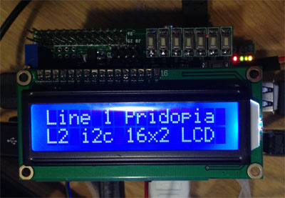
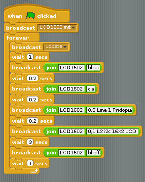
command "LCD1602 " + "init" initial
i2c 16x2 LCD
command "LCD1602 " + "X , Y " + " MESSAGE"
Display message to LCD in location x,y
command "LCD1602 " + "cls" clean screen
command "LCD1602 " + "bl " + "on/off"
LCD back light ON / OFF
command "LCD1602 " + "X , Y " + " wip"
Display WiFi IP to LCD in location x,y
command "LCD1602 " + "X , Y " + " eip"
Display Ethernet IP to LCD in location x,y
command "LCD1602 " + "X , Y " + "
time"
Display Time to LCD in location x,y
command "LCD1602 " + "X , Y " + "
date"
Display Time to LCD in location x,y
16x2 LCD RSS function
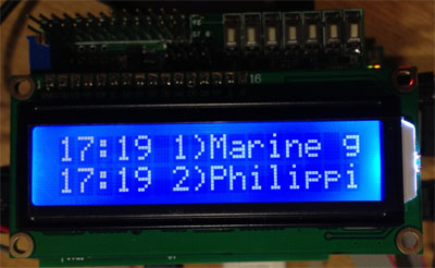
RSS function ( Scrolling text Display top 4 News
message)
message format
Line1 --> Time + message 1 + " ->-> "
+ Message 3 + Time
Line2 --> Time + message 2 + " ->-> " +
Message 4 + Time
BBC world news RSS feed
command "LCD1602 init" initial i2c
16x2 LCD
command "LCD1602 bl on" turn on LCD back light
command "LCD1602 "rss"+ " speed" Active RSS function
(need have internet)
LCD1602 rss 8
speed (1 to 20 - 1 is fast , 20 is slow)
command "LCD1602 rss off" stop RSS function
(4) i2c LCD1602 & LCD 2004 8 switch detect in scratch
(1) broadcast "LCD1602 init"
for 16x2 LCD
broadcast "LCD2004 init"
for 20x4 LCD
(2)after broadcast "Update"
in Sensing --> Slider , you will see the "
I2C1,I2C2,I2C3,I2C4,I2C5,I2C6,I2C7,I2C8 " in the list
18. Demo 18 spi 23s17-4 64 GPIO &
64 LED output test
spi 23s17-2 32 GPIO & 32 LED output test
 U1 to U4 spi 23s17 address 40,42,44,46
U1 to U2 spi 23s17 address 40,42
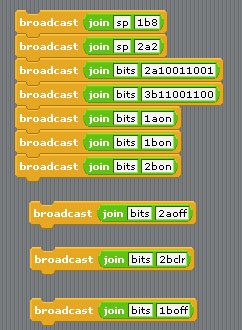
40 --> 1 42 --> 2 44 --> 3 46 --> 4 48 --> 5 4a --> 6 4c --> 7 4e --> 8 Command "sp"+ "address(1-8)" + "a" +"bit(1 to 8)" for Port A Command "sp"+ "address(1-8)" + "b" +"bit(1 to 8)" for Port B Command "bits"+ "address(1-8)" + "a" +"bit(8 to 1)" for Port A Command "bits"+ "address(1-8)" + "b" +"bit(8 to 1)" for Port B sp2b7 --> spi address 2 Port B bit 7 ON/OFF sp3b4 --> spi address 3 Port B bit 4 ON/OFF bits2b01010101 --> address 2 port B from bit 8 to 11 output --> 01010101 bits2a01010101 --> address 2 port A from bit 8 to 1 output --> 01010101 bits2aoff --> address 2 Port A all OFF/clear bits2aclr --> address 2 Port A all OFF/clear
19. Demo19 spi 23s17-8 128 GPIO test 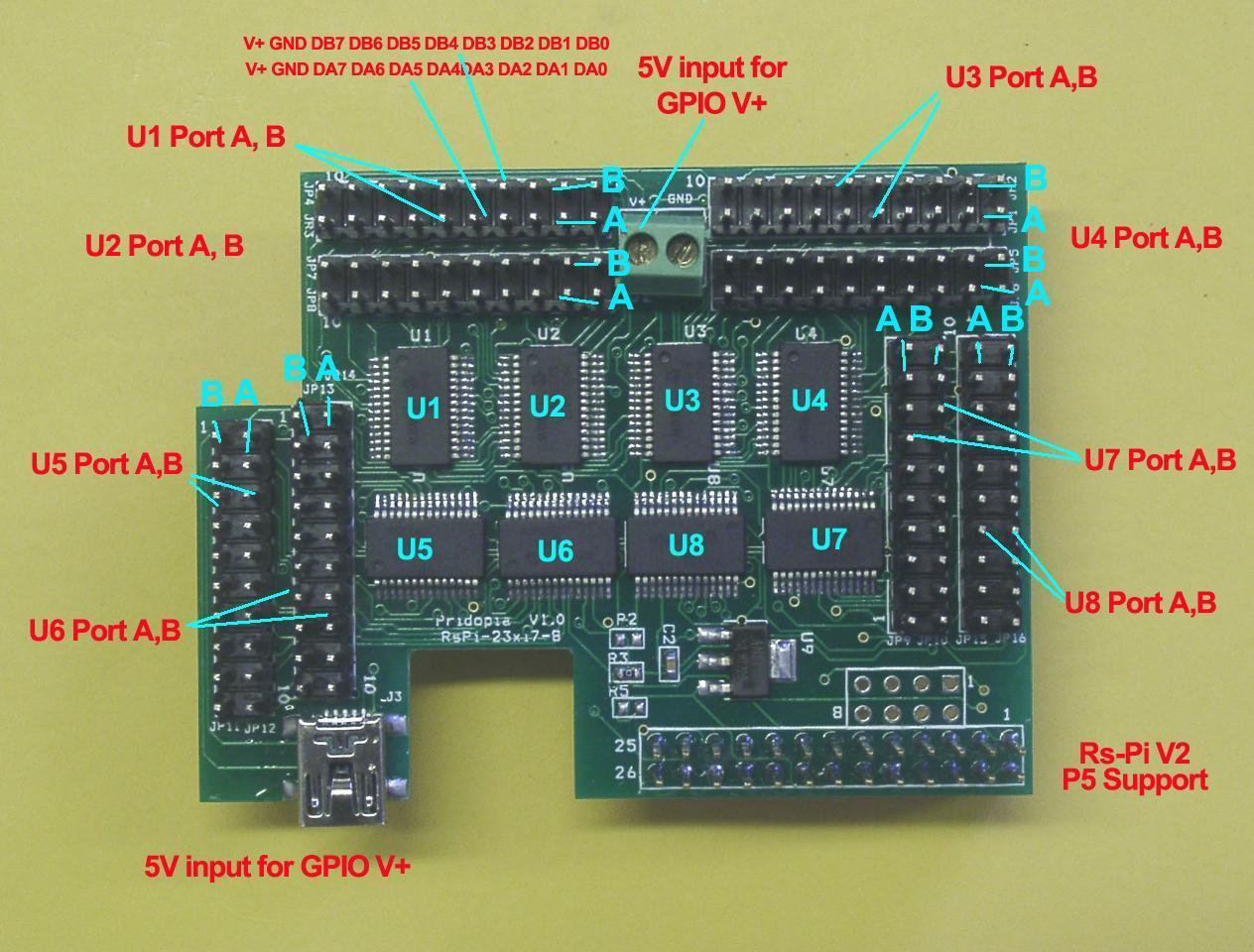 U1 to U4 spi 23s17 address 40,42,44,46
U5 to U8 spi 23s17 address 48,4a,4c,4e
40 --> 1 42 --> 2 44 --> 3 46 --> 4p; 44 --> 3 46 --> 4
48 --> 5 4a --> 6 4c --> 7 4e --> 8
Command "sp"+ "address(1-8)" + "a" +"bit(1 to 8)" for Port A
Command "sp"+ "address(1-8)" + "b" +"bit(1 to 8)" for Port B
Command "bits"+ "address(1-8)" + "a" +"bit(8 to 1)" for Port A
Command "bits"+ "address(1-8)" + "b" +"bit(8 to 1)" for Port B
sp5b7 --> spi address 5 Port B bit 7 ON/OFF
sp7b4 --> spi address 7 Port B bit 4 ON/OFF
bits2b01010101 --> address 2 port B from bit 8 to 11to 11
output --> 01010101
bits8a01010101 --> address 8 port A from bit 8 to 1
output --> 01010101
bits2aoff --> address 2 Port A all OFF/clear 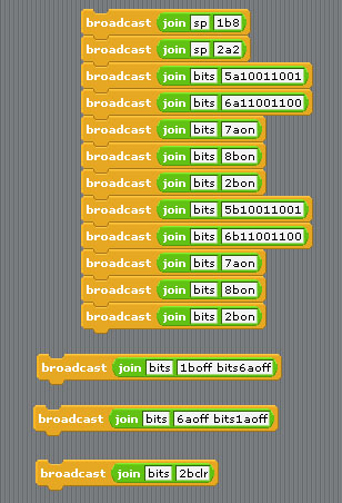 20. Demo20 spi MCP3002 /MCP4802 AD/DA (1)MCP3002 ADC 10 bit Analog-to-Digital Converter output J11 (Vcc, AD0, GND, AD1) 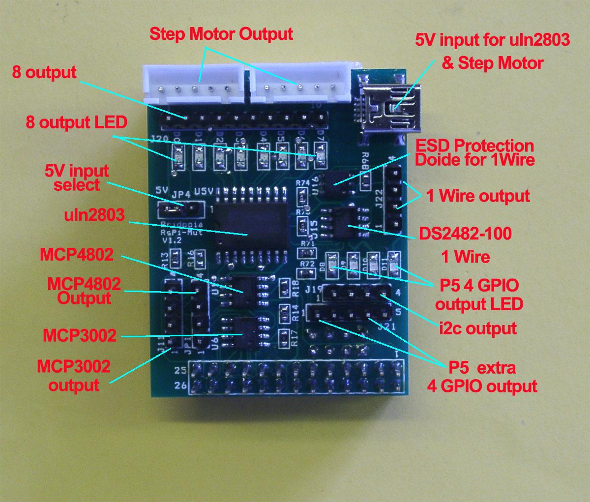 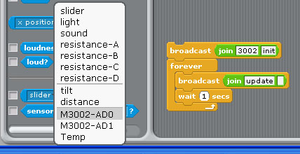 command "3002init" initial spi mcp3002 broadcast "Update" in Sensing ---> Slider ,
you will see "M3002-AD0, M3002AD1" in the list 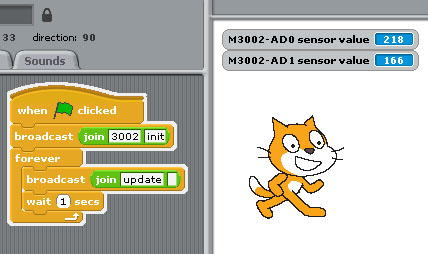
(2)MCP4802 DAC 8 bit Digital-to-Analog Converter output JP1 (DA0,GND,DA1,GND)
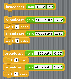 command "4802init" initial spi mcp4802 command "4802out" + (a or B ) + output voltage a -- DA0 , b -- DA1 (output voltage range 0.01 to 2 ) | 

 Scratch V1.4
in
Raspberry Pi GPIO control
Scratch V1.4
in
Raspberry Pi GPIO control